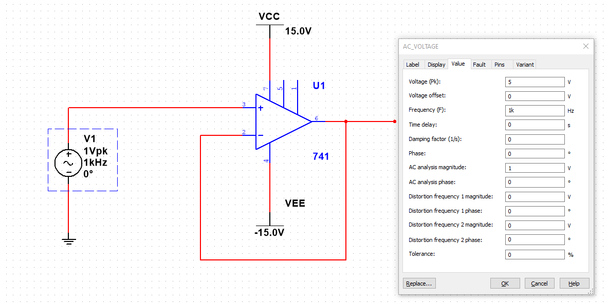

Corresponding experimental results are completely consistent with the theoretical analysis. Further, the hyperchaotic system is implemented by analogue circuits. Additionally, the symmetrical coexistent attractors are investigated. Dynamic analysis shows that it has infinite equilibrium points and multistability. (There's a step-by-step tutorial on how to get input and output impedances here.A novel hyperchaotic circuit is proposed by introducing a memristor feedback in a simple Lorenz-like chaotic system. The output impedance is about \$800 \ \Omega\$. If you run this simulation, you'll get this plot for output impedance: And then we'll plot MAG(V(I1.nA)/I(I1.nA)) to see the output impedance: We'll set this current source to have 0 current at DC so that it's only being used as a small-signal current source, pushing and pulling current from the output node. In this case, by mousing over the plot, you'll find that it's about \$2 \ \text\Omega\$ in the pass band:įor output impedance, we need to modify the circuit slightly, just by adding a test current source connected to the output. Input impedance is easy: we can just take the same circuit above and instead plot the expression MAG(V(V1.nA)/I(V1.nA)), which looks at the small-signal current relative to the small-signal voltage on source V1 and plots their ratio, an impedance. (If you need to recreate this on your own, there's a step-by-step tutorial on how to draw a circuit and get the voltage gain Bode Plot here.) Input Impedance If you open the circuit above and run the simulation, you'll get the following Bode Plot showing approximately +30 dB of gain in the pass band: Simulate this circuit – Schematic created using CircuitLab I've quickly drawn your circuit and set it up to get the Bode plot of voltage gain, setting up a frequency domain simulation with V1 as the source and DB(MAG(V(out))) and PHDEG(V(out)) as the plot outputs: I don't use Multisim, but it's easy to find an amplifier's voltage gain and input and output impedances with the CircuitLab circuit simulator.


 0 kommentar(er)
